4.7 IGNITION DEVICES
The initiation of the release of the chemical energy stored in liquid rocket propellants is accomplished by a number of methods from which the engine designer will select the most suitable for a particular system: (1) Igniters (2) Hypergolic ignition (3) Catalysts
All of these methods have been in use for both thrust chambers and gas generators. Note that in liquid propellant rocketry, gas generators have been used not only for turbine power but for propellant-tank pressurization as well. The selection of the preferred ignition method depends on the chosen type of propellants, whether bipropellants or monopropellants are used, on the size of the combustion chambers, the heat release per unit time required in relation to the amount of propellants entering, and on a number of other considerations which will be discussed.
All ignition methods, particularly those for bipropellant systems, have one overriding requirement in common: minimum ignition delay.
If the propellants entering the combustion chamber are not promptly ignited, explosive mixtures can form and detonate with damaging results. The assurance of faultless ignition is dependent on the selection of the ignition method, the quality of design, and on adequate heat release.
Igniters
These are defined as devices which release heat and thus initiate tie reaction of the main propellants which subsequently sustains itself. Igniters derive their power from an outside source or from a limited amount of energy stored as solid propellants within themselves. Following ignition, igniters do not participate further in the combustion process. Some of the principal igniter types are discussed below.
Pyrotechnic Igniters
These are literally slow-burning fire crackers, somewhat modified for rocket engine application. Burning time is in the range of a few seconds. For thrust chamber use they can be mounted to the injector face or inserted from below at the end of a wooden or plastic stick (fig. 4-2). For better heat distribution, multiple units firing in different directions, have been used, as a rule radially outward from the center across the injuctor face. In other designs they have been mounted to pinwheels, achieving distribution through rapid rotation.
Although pyrotechnc igniters are used, they should be considered obsolescent. To achieve adequate heat release for modern large engines, their size becomes impractical. Also, ejection of their inert parts can cause damage to the delicate thin-walled tubes of modern chamber walls. Under cryogenic conditions, they have exhibited a tendency to cause ignition delays, complete duds, or explosive popping.
Pyrotechnic igniters for gas generators and small thrust chambers have been mounted in recesses as screw-in-type plugs. (See figs. 4-53 and 4-54.) The igniters are initiated by electrically triggered squibs, of which there are a variety of types in use. The need to connect wires to the pyrotechnic igniters is another inconvenience. Furthermose, checkout of the integrity and readiness of pyrotechnic igniters is difficult. It is one of the inherent shortcomings of solid propellants that they cannot be switched on briefly for checkout and then stopped again.
 Figure 4-53.-Radially outward firing pyrotechnic igniter for center of injector mounting.
 Figure 4-54.-Gas generator igniter with built-in fusible link.
Assurance of their reliability, therefore, is by statistical and sampling methods. For operational application, additional safety margins are secured by redundancy. However, this tends to increase bulkiness further. Also, pyrotechnic igniters are unsuitable for repeated starts.
Engine manufacturers aave been procuring pyrotechnic igniters from sources specializing in this field. Typical examples of selected parameters are as follows:
For a 150000 -pound thrust, LOX/RP-1 engine:
Main chamber: centrally mounted unit; propellant weight, burning time; heat release, ; perchlorate-type fuel. Electrically initiated. (Later models of this engine used hypergolic slugs.) Gas generator: Pyrotechnic: propeliant weight, burning time; heat release, 1.6 Btu/sec; perchlorate-type fuel. Vernier engines (earlier models only): Similar to gas generator units. It is vital that certain of the specifications fall within a stated band. For instance, it can be specified that in a family of samples no igniter will fire at currents below 1 amp , and that all musi fire below 4 amp . The first condition concerns the avoidance of accidental firing due to stray currents introduced by extraneous RF signals or other sources; the latter is simply a reliability requirement. Similarly, minimum and maximum burning times, i.e., tolerances of the nominal times, will is dictated by startsequence conditions.
In operational designs, the pyrotechnic i,niters frequently do not ignite the main propellants directly, but ignite a pilot flame fed by a small portion of the main fuel. The pilot flame then ignites the main propellants.
Hypergolic Igniters
The term "hypergolic" was coined by the German chemist Noeggerath about 1942 and is composed of elements of the Greek words for "high energy liquid." The term now denotes a bipropellant combination which ignites spontaneously when the two components meet. Such a system was used as 24 ignition source for the earlier German A-4 angine (later called V-2 engine), utilizing hydrazine-hydrate ( ) and 80 percent hycirogen peroxide . Thin tubes supported by a wooden stick were iniverted into the thrust chamber from below. Upon an "ignition" signal, a ground-mounted supply unit, including remotoly operated valves, fed the two components to aear the injector elements where they burned with a spontaneously igniting hot Clame. This method may also have been used temporarily on other systems. However, its clumsiness, the frequent clogging of feed lines, and the need to eject a considerable amount of inert solid material made it undesirable. Also, adaptation to repeated starts would be complex and would require vehicle mounting, thus adding inert flight weight.
Hypergolic Slugs
A more elegant way of using the hypergolic effect for main-propellant ignition is through use of a hypergolic slug. In this design a small amount of fluid is used which is hypergolic with one of the main propellants but not with the other. The fluid is stored in a cylindrical cartridge which has burst diaphragms at either end. The cartridge, in turn, is loaded into a housing which is part of a bypass line paralleling a highpressure main propellant feed line (fig. 4-55). If a fluid is chosen which is hypergolic with the oxidizer but neutral to the fuel, it is installed in the fuel system, and vice versa. The former type is the more common one. Here a fuel bypass line feeds an injection element in the center of the injector, or a set of elements evenly distributed over the injector face. When the pumps start and outlet pressures rise, the oxidizer valve is opened. As pressures rise further, the burst diaphragms in the hypergolic-fluid container rupture and the fluid meets with the oxidizer in the chamber, igniting spontaneously. The fuel following the slug sustains the ignition flame. The main fuel vaive is then opened and all parameters reach main-stage level. Since the igniter elements carry fuel fed from the main source following ignition, they continue to participate in the combustion, undistinguished from the remainder of the main injector. (See schematic, fig. 2-13.)
 Figure 4-55.-Hypergol slug cartridge and housing.
Typical of fluid hypergolic with oxygen is triethyl aluminum. For optimum behavior, i.e., for animimum ignition delays and avoidance of undesirable deposits in fuel and sensing lines, optinum mixtures of the two have been successfully established experimentally. In a typical application, an amount of 6 cubic inches has been found adequate, although 9 cubic inches are actually used for maximum safety margin. By comparison, a 1.5 -million-pound thrust engine uses 35 cubic inches. The hypergolic slug method, first explored at the German Peenemünde installation, is well developed and has found wide application. Limited design and development work has been done more recently toward repeated-start units, using a device resembling an automobile brake master cylinder with its replenishing features. However, the hypergolic slug is truly a single-start device. Because of relative bulkiness, the hypergolic slug is not recommended for small units such as gas generators, where pyrotechnic igniters or spark plugs are preferred.
Spark Plugs
Spark plugs and their accessories have been developed to high levels of efficiency and reliability for liquid rocket engine use. They are eminently suitable for repeated starts. For direct ignition, however, they are confined to relatively small combustion devices. (Ses fig. 4-56.) In a typical 200000 -pound thrust engine, the gas-generator spark plugs fire at the rate of 50 sparks per second, releasing approximately joule per spark. This corresponds to 5 joules or per plug. The efficiency of spark generation from the electrical
 Figure 4-56.-Spark igniter assembly. At right, screw-in spark plug; at left, cable connector.
storage device is approximately 20 percent. The overall efficiency of the spark ignition system is approximately 10 percent. Thus, 100 watts of electrical power is required. If a source is used, the nominal current is 4 amp when two redundant systems are used in parallel. A Typical voltage at the spark plug is 15000 V .
Augmented Spark Igniters
The limitation of direct spark ignition to small units has led to the design and development of augmented spark igniters (ASI). In this design a spark plug, similar to the above, fires into a small chamber about the size of a gas generator. A small amount of the main propellants is fed into this chamber where they ignite. The hot flame generated in turn ignites the main propellants. Figure shows the principles of an earlier augmented spark igniter design. Permanently located at the injector end of the thrust chamber, this igniter directs its products of combustion across the face of the main injector. It is film cooled by the tangential injection of fuel. The oxidizer is injected through two copper tubes which impinge at the centerline of the igniter, resulting in a hot-core type of combustion. The igniter is made of 4130 steel and has a convergent, throatless nozzle. This results in a wide dispersion angle of gases emanating from the nozzle. The igniter is capable of an unlimited number of starts, since the spark plug is so located that the combustion does not seriously affect its life. The igniter has proven operable over a wide range of mixture-ratio and pressure conditions. It continues to operate throughout
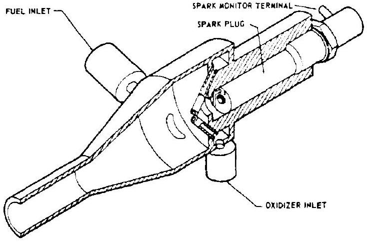 Figure 4-57.-Augmented spark igniter.
main stage, which prevents any of the main chamber gases from backing up into the igniter. Approximately one-half percent of the main propellant flow rates has been found adequate for the augmented spark igniters.
Special Designs
For the engine used in the Saturn S-I booster, gas-generator ignition by the solid-propellant turbine spinner has been successfully developed. The turbine spinner will be discussed in a later chapter.
Hypergolic Main Propellant Ignition
In preceding paragraphs it was learned that hypergolic fluids are being used as ignition sources for main propellant combinations which by themselves are not hypergolic (i.e., "anergol" propellants). Hypergolic liquid main propellants have attracted attention since the early days of modern rocketry. Their use permits a substantial simplification of the engine system through elimination of the entire ignition system, leaving entry timing the only functional requirement. This gain however, is not entirely without penalties. The practical hypergolic propellant combinations have a somewhat limited specific impulse. Furthermore, some are highly corrosive and/or pose handling and storage problems which the engine designer has to consider.
A number of hypergolic main propellant combinations have been in successful operational use for many years. During World War II, several guided-missile systems using hypergolic propellants, were under development in Germany. Hydrazine hydrate ( ) and high-percentage hydrogen peroxide were used in certain Messerschmitt rocket fighters and the antiaircraft missile Enzian. Amines and nitric acid were used for the AA rocket Schmetterling. Optolines and nitric acid with sulfuric acid additives (approximately 10 percent were applied in the Peenemünde developments of the antiaircraft rocket Wasserfall ( 17000 -pound thrust) and the small 1300 -pound Taifun. "Optoline" was a generic term for various mixtures of aniline, hydrocarbons, and other substances.
In the United States, several propulsion systems utilizing hypergolic propellants have been developed.
To make available to the high performing but anergol propellant combinations the simplicity of hypergolic behavior, the effectiveness of small amounts of additives ("sweeteners") has been successfully demonstrated.
Catalysts
In a general sense, catalysts are not igniters but initiators and sustainers of reactions, which themselves remain unchanged during these reactions. In rocketry, catalysts have been used predominantly to initiate and sustain the composition of monopropellants ("Monergols"), notably that of hydrogen peroxide. Several operational or near-operational systems existed during World War II, such as the earlier Messerschmitt Me-163 which used hydrogen peroxide with potassium permanganate solution as the catalyst. Probably the most widely used application of this principle during that period was for the turbine steam-generating system of the German A-4 (later called V-2) ballistic missile, which employed 80 percent hydrogen peroxide with either potassium permanganate or sodium permanganate as catalysts.
Because of the need for relatively elaborate timing, valving, and interlocking devices, the use of liquid catalysts was soon found to be cumbersome and undesirable. Application of solid catalysts, therefore, as they were being used for underwater torpedoes, led to design and development work toward use of these systems for rocket application. They never reached maturity for the German World War II systems, but were perfected after the war by the British and to a limited degree by the United States. The Redstone rocket steam plant, using solid catalysts, has consistently and successfully operated in many flights, among them the first U. S. manned rocket flight by Commander Shepard. Another successful development are the AR airplane superperformance rockets. Analogous to certain British systems; the AR systems decompose hydrogen peroxide fed through a solid catalyst bed consisting of impregnated wire screens. Since the specific impulse of decomposed hydrogen peroxide alone is low (below 200, depending on concentration and design parameters), RP fuel is injected below the decomposition chamber. Because of the sufficiently high temperature of
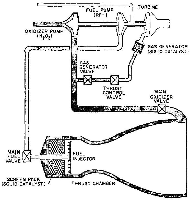 Figure 4-58.-Schematic of a Rocketdyne AR-1 superperformance rocket engine.
the decomposition gases ( ), the RP ignites and burns spontaneously with the free oxygen of the decomposed . (See fig. 4-58.) In this manner, the solid catalyst indirectly serves as an ignition system. While the specific impulse with RP afterburner is still moderate (approximately 245 seconds for the AR), these systems offer great versatility, storability, and extreme simplicity, including throttling to low levels and restartability.
More recently, it has been successfully demonstrated that catalytic operation offers a simple alternative to augmented spark ignition for hydrogen systems.
In a process patented for Engelhard Industries, Newark, N. J., a gaseous mixture of oxygen and hydrogen is fed through a catalyst bed of palladium-impregnated alumina ( ) pellets, by which the mixture is ignited. Installation of this igniter is similar to an augmented spark igniter.
Ignition Detection
The reader familiar with the news stories about rocket launchings over the past years is well aware of the consequences of rocket stages failing to ignite: loss of mission. This is equally true for liquid- and for solid-propellant systems. With the former, however, an additional hazard exists in case of ignition failure: that of accumulation of explosive propellant mixtures which can be accidentally set off with catastrophic consequences. This consideration has always been a concern with unmanned vehicles. but has become even more important for manned ones.
Recognition of these potential dangers has prompted extensive investigation of means to detect reliably absence or presence of ignition in liquid propellant rocket engines. Only upon an "ignition OK" signal should the engine-start sequence be permitted to proceed. This refers mainly to the thrust chamber. For gas generators, redundancy appears to be adequate protection for most applications. Desirable detection systems must judge ignition both qualitatively (absence or presence) and quantitatively (adequate heat release). Not all methods are equally good in both respects.
In some form or another, the engine designer will have to provide means for ignition detection. A survey follows of several which have found operational application.
Visual Detection
For the German A-4 (V-2) and the early U. S. Redstone missiles, visual observation by the test conductor was used. Man in this case was the interlocking device and would initiate the next sequence step only if, in his judgment, ignition was adequate. This simple procedure was satisfactory because these early systems employed a prestage, during which the main propellants were admitted under tank head only. The resulting relatively low flow rates were then increased by starting the turbopump upon a "prestage OK" signal.
With the increasing size of modern rocket engines, visual observation became unreliable. The type of installation of these systems in static firing stands and on launch tables made direct observation difficult. Furthermore, improved igniters, developed to keep the ignition flame concentrated where it should be, i.e., at the injector face, resulted in little or no visible fire emerging at the chamber exit. With the disappearance of the prestage step, the visual problem increased because of the large amount of oxidizer present in full flow ignitions which shrouds the ignition flame. Thus, means had to be found to detect ignition by other means.
Optical Detection
Ground-mounted optical devices can be moved up close to the chamber exit. A number of types have been investigated, such as simple light or infrared-sensitive cells. They were found, however, to be subject to the limitations mentioned for human observers. It is possible to mount the optical devices into the chamber wall facing toward the inside near the injector face; however, the devices used thus become vehicle mounted and require interfaces to ground-support equipment. Also, "windows" in the chamber wall represent undesirable surface discontinuities. It is unlikely, therefore, that optical devices will find wide application for ignition detection.
Pyrometers
Heat-sensitive pyrometers are closely related to the optical devices and subject to the same limitations.
Fusible Wire Links
For many applications these are simple and reliable devices. A wire is strung across the chamber exit which, when fused by the ignition flame, interrupts a circuit and signals "ignition OK." Through proper selection of wire gage, material and distance from the chamber exit and/or center, some quantitative judgment is obtained. The wire can be ground mounted or chamber mounted. It must be isolated and should have spring loading, like the well-known electric fuses, to assure positive separation.
Wire links have a number of shortcomings. The fused wire ends may touch other metal parts and thus reconnect the circuit before the relay drops out. Suitable circuitry and mounting must therefore be applied. If a pyrotechnic igniter is used, the wire can be broken by inert particles, or even by a dud igniter coming out of the chamber, giving an incorrect "ignition OK" signal. This has been overcome by providing redundancy using several wires in parallel, all of which must be broken before the sequence can proceed. In another design the wire has been mounted as a loop placed in a groove on a wooden or plastic stick. It is thus supported against all reasonably expected mechanical damage and adequate insulation is maintained after fusion.
Pressure-Sensing Devices
Because of the need to mount the fusible wires at the exit of the thrust chamber, they are subject to some of the limitations noted for visual and optical methods. It has been attempted, therefore, to sense the pressure rise in the combustion chamber resulting from the burning igniter flame. However, since the pressure rise is small (a few psi at best), reliable discrimination is difficult. Furthermore, the sensing-pressure switches must be able to withstand the much higher pressures during subsequent main stage. Pressure-sensing devices have potential for multistart engines.
Resistance Wires
Another method designed to overcome the shortcomings of fusible wire links is the application of resistance wires. Constructed like a glow plug and connected to a bridge circuit, the resistance wire will signal by a distinctly different resistance in the presence or absence of ignition. The art is to find that spot in the thrust chamber or gas generator which experiences a clear temperature rise as a function of ignition, yet remains cool enough to prevent fusion of the wire. Resistance-wire sensors are ideally suited for repeatable start engines.
Indirect Methods
In conjunction with hypergolic slug ignition, other approaches to ignition sensing have been developed. In one design an electric contact assures that a cartridge is actually installed. This does not assure, however, that the cartridge is loaded or completely loaded, nor that the downstream lines are not clogged or that the diaphragms will burst. Weighing of the cartridge and purging of all lines must be included in the firing preparation.
In another arrangement a pressure switch senses pressure buildup in the igniter injection line upon rupture of the hypergolic fluid cartridge burst diaphragms. The switch signal then initiates the next sequential step. A modification of the system substitutes a pressure-actuated valve for the switch with similar effects. This method does not assure, however, that the cartridge is properly filled with the right amount of the correct fluid.
Spark igniters use electric devices which ascertain that the plug is sparking based on conductivity effects due to ionization near the electrodes.
The methods in the above list, which undoubtedly is not complete, are described as indirect because none of them directly and reliably detects ignition; i.e., the release of adequate heat. This is a drawback and cannot entirely be offset by weighing, certifying, and inspecting.